I occasionally hear from customers who report a discrepancy between measurements made on their Briffidi SW1 and a machine used in a professional shop. Usually, they assume that the other machine is correct, but this is not a good assumption. In order to make the SW1 accessible, I made design choices that affect ease of use and appearance, but as an engineer with no one pressuring me to make compromises, I did not compromise on measurement accuracy and precision. This article will discuss possible sources of discrepancies between swingweight machines.
Calibration and Leveling
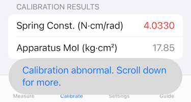
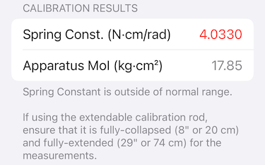
All swingweight machines must be properly leveled and calibrated. If the pivot axis of the machine is not nearly perfectly vertical, gravity will affect the measurement results. Periodic calibration is also necessary. The stiffness of the spring(s) that drives the machine changes with temperature, so a machine calibrated in the summer will under-report swingweight when used in the winter. It’s possible that some machines have temperature sensors and compensation logic, but most, including the SW1, probably do not.
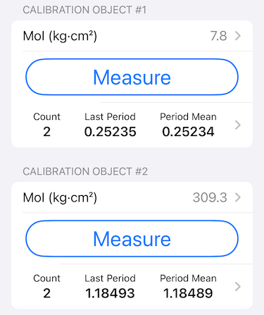
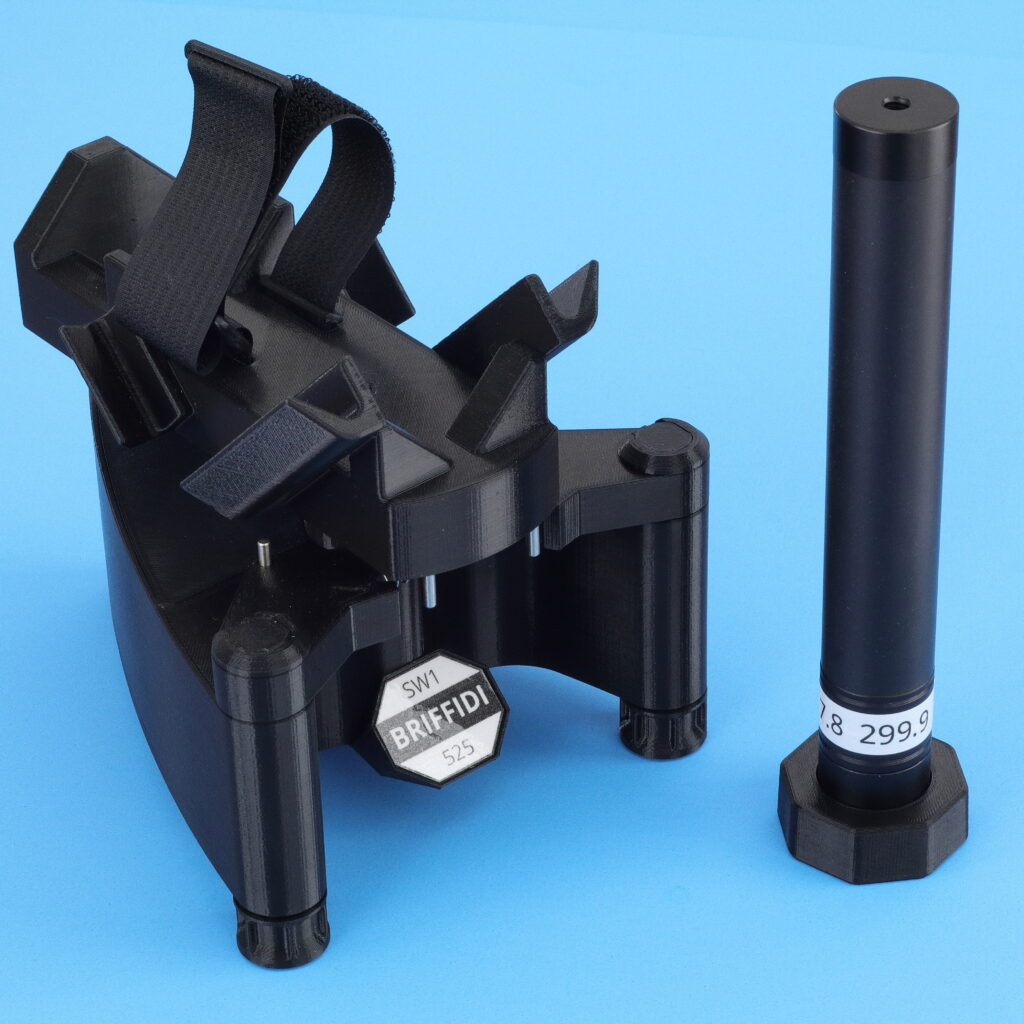
Swingweight machines are calibrated with objects of “known” swingweight. I’ve estimated that the SW1 calibration rod values are accurate to within ±0.6 kg·cm². The Dunlop machine I tested had a calibration rod marked as 200±1 kg·cm². Any discrepancy between the actual and marked values will directly affect measurement accuracy.
Pivot Axis Location
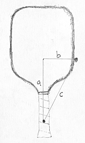
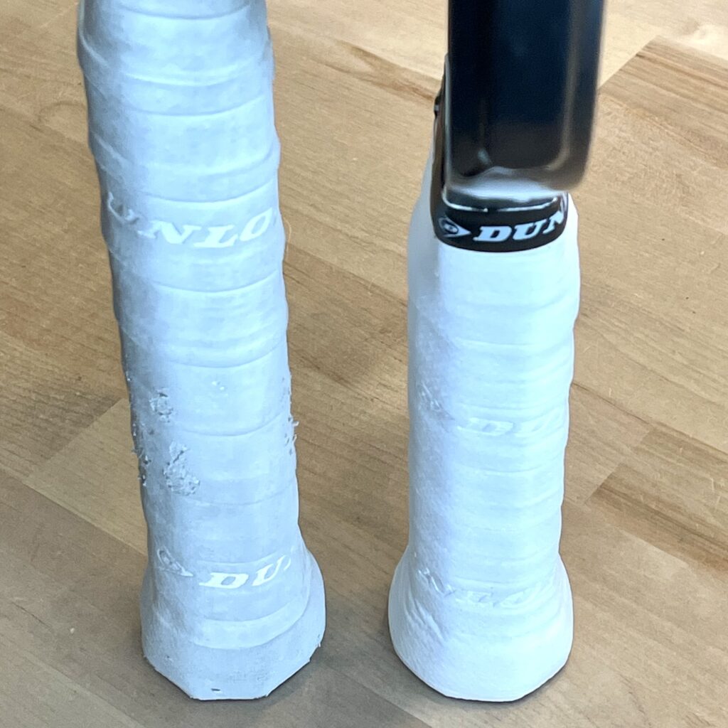
The SW1 uses a pivot axis that is 10 cm from the butt end of a racquet. Some machines use a location of 4 inches, or 10.16 cm. Compared to a measurement taken at 4 inches, a typical racquet will measure about 2.5 kg·cm² higher at 10 cm.
For pickleball paddles, some newer machines are capable of measuring paddles at the standard tennis location. The SW1 with Pickleball Adapter uses a 5 cm axis location. Measurements at the tennis location will be much lower.
Measurement Linearity
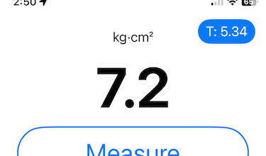
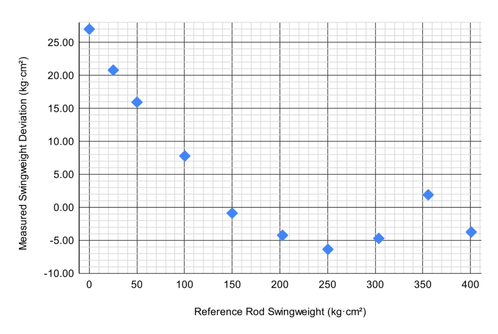
The SW1 is very linear across a large measurement range. I previously reported the results of linearity testing in Briffidi SW1 Linearity Testing. I shared the results of the same testing with a Dunlop machine in Dunlop Swingweight Machine Linearity Testing. There is similar data for a Babolat RDC in the journal article Measuring the Inertial Properties of a Tennis Racket by Spurr. These data are each samples of just one machine, but the SW1 exhibited much better linearity across the tested ranges. One simple way to check linearity is to take a measurement with the cradle empty. It should measure close to zero. The Dunlop machine I tested reported a swingweight of 27 kg·cm² when empty.
Swing Speed and Air Resistance
There is no standard for the oscillation arc and spring torque used to measure swingweight. With a larger arc and/or higher spring torque, the racquet will move more quickly through the air, increasing air resistance. Further, strung racquets will create more air resistance than unstrung racquets. Air resistance will slow the oscillation, resulting in slightly over-reported swingweight.
Measurement Validation
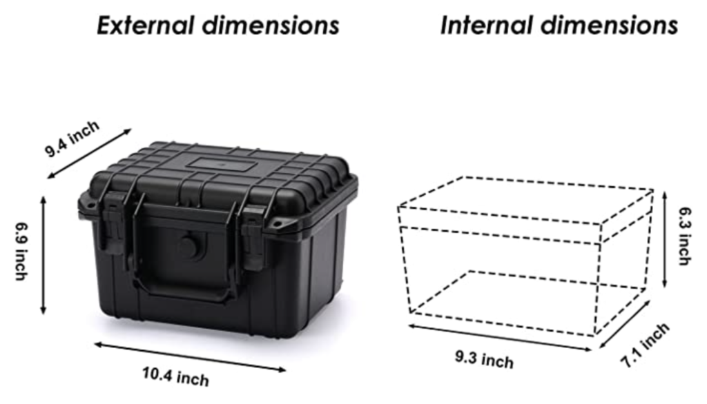
The only way to check the accuracy of a swingweight machine is with objects of known swingweight. Such objects can be created with PVC pipe or other rod/pipe, though care is required to know the swingweight to a high degree of accuracy. The ends must be cut or faced cleanly and squarely. Then, the mass and length of the rods must be measured precisely with accurate tools.
You can use the calculator below to calculate the swingweight of a pipe or rod with length and mass measurements. To determine the length for a target swingweight, set the material density and then iterate the length to hit the target. After you have a cut length of pipe, directly enter the measured length and mass to see the resulting swingweight.
The calculator first determines the moment of inertia about an axis through the center of mass using the formula:
I = ( 1/12 )m( 3( r₂² + r₁²) + h² )
where I is the moment of inertia, m is the mass of the pipe, r₂ is the outside radius, r₁ is the inside radius, and h is the pipe length. If using a solid rod, use zero for r₁.
Then, it translates the moment of inertia to the swingweight axis using the parallel axis theorem as:
SW10cm = I + m( h/2 – 10 cm )²
The “10 cm” is the pivot location.
Summary
Differences in swingweight measurements can be caused by calibration, leveling, pivot location discrepancies, machine non-linearity, and air-resistance effects. When properly calibrated and used as designed, the Briffidi SW1 excels at measurement accuracy and linearity, even when compared to machines commonly assumed to be authoritative.