I’ve seen some confusion about PBCoR (Paddle Ball Coefficient of Restitution for Pickleball), so I thought I’d attempt to explain it a bit. I’m a mechanical engineer but not an expert in impact dynamics, so if you have feedback, please leave a comment.
Coefficient of Restitution
Coefficient of restitution (CoR) is a measure of the elasticity of a collision. It is the ratio of the relative separation velocity after the collision to the relative approach velocity before the collision1. A collision with a CoR of one (1.00) would be perfectly elastic, and the relative velocities before and after the collision would be equal.
One Body Fixed
When one body is fixed, or its motion is negligible, CoR reduces to the exit speed of the moving object over its incoming speed. This is the case for pickleball ball testing, where a ball is dropped onto a heavy granite slab. It’s dropped from a height of 78 inches and must rebound to a height between 30 and 34 inches. Neglecting air resistance, when a ball drops to the slab, it will have a velocity of 13.95 mph at impact. To reach a mid-specification rebound height of 32 inches, it must rebound at a speed of 8.93 mph. So, the CoR of the collision is 8.93/13.95 = 0.64.
Note: To keep things simple, I used the bottom of the ball as the reference for height, though the actual rebound height specification is to the top of the ball. The reference (top, bottom, or center) for the drop height is not specified.
Both Bodies Free
When a swinging paddle contacts a ball, the collision changes the velocity of both bodies. The changes are dependent upon the masses, velocities, and the CoR1 of the collision. The velocity of the less massive body will change more than that of the more massive body, so the paddle will slow a bit, but the ball velocity will change a lot.
Paddle Effective Mass
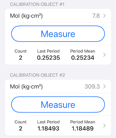
Players don’t typically hit the ball at the center of mass of a typical paddle, as it excites a vibration in the paddle that robs energy and feels bad. Because off this, the effective mass of the paddle is lower than its actual mass. If we assume that a paddle is rigid, we can calculate its effective mass at any location using the mass properties of the paddle: static weight, balance point, and swingweight. The PBCoR test includes procedures for finding these mass properties, and the effective mass is used in the PBCoR calculation.
PBCoR Measurement
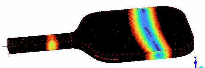
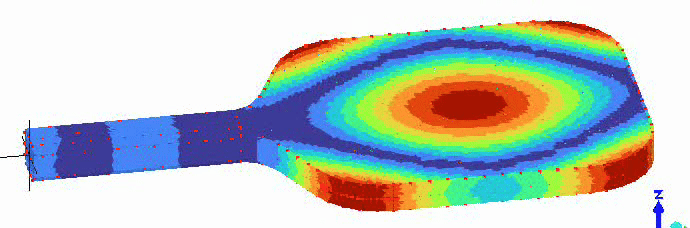
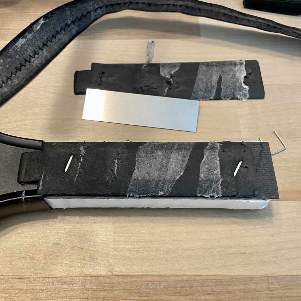
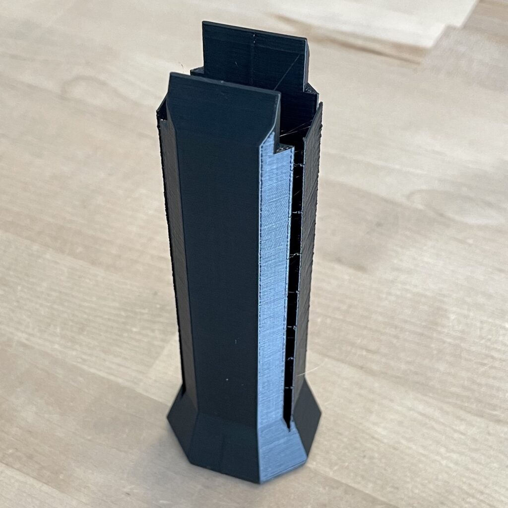
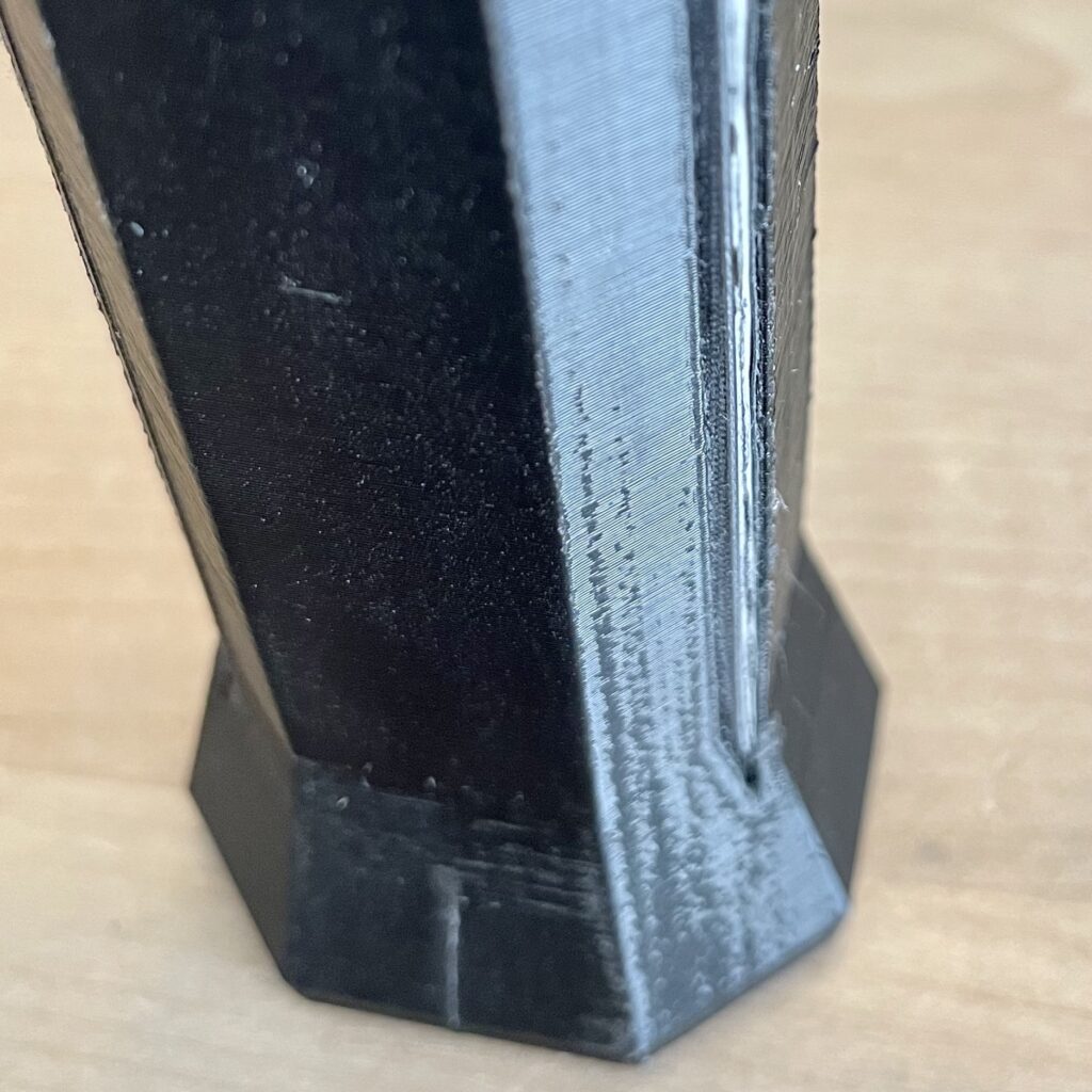
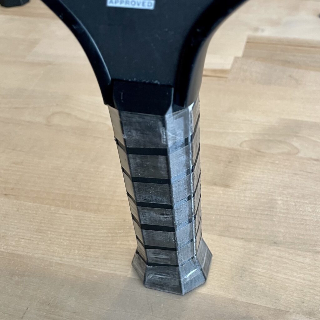
To measure PBCoR, a ball is fired at a stationary paddle at 60 mph. The paddle is clamped horizontally as shown in Figure 1.
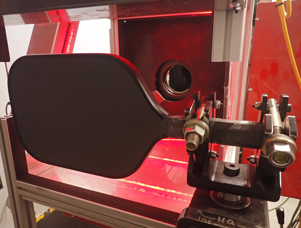
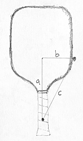
The clamp is free to rotate about an axis two inches from the handle end of the paddle (with end cap removed). For a typical paddle, the instantaneous recoil of the paddle from a ball collision is approximately rotation about that axis. Technically, the typical ball collision location is approximately at the center of percussion (CoP) of the clamp rotation axis. The paddle is effectively free to recoil.
To start, the ball is fired at the CoP location, and an algorithm is used to seach on either side of the CoP for the location with the highest PBCoR, which is calculated as:

Where:

Where:
- PBCoR: Paddle Ball Coefficient of Restitution
- Vi: Inbound velocity
- Vr: Rebound velocity
- m : Test ball mass
- I : Moment of inertia of paddle (about clamp pivot axis)
- Ip: Moment of inertia of clamp (about clamp pivot axis)
- Q: Distance from the impact location to the clamp pivot axis
What Does it Mean?
The CoR of impact is probably non-linear with respect to velocity. That is, the CoR is probably different for different incoming relative velocities. Is 60 mph a good choice for testing? A 60 mph relative velocity could be a paddle traveling at 60 mph impacting a stationary ball, or it could be a paddle at 25 mph impacting a ball traveling at 35 mph in the opposite direction. The former might be a very fast serve, and the latter seems reasonable for a hands battle. At a PBCoR limit of 0.43, the relative rebound velocity from a 60 mph impact would be 60 * 0.43 = 25.8 mph.
Considering the serve example, a typical paddle would slow from 60 to 48.8 mph, and the ball would accelerate to 74.6 mph [60 – 0 = 60 and 74.6 – 48.8 = 25.8]. In the hands battle example, the paddle would slow from 25 to 13.8 mph, and the ball would reverse direction and leave at 39.6 mph [25 – (-35) = 60 and 39.6 – 13.8 = 25.8]. Is that reasonable? I haven’t tried to analyze footage to determine the speeds involved. For comparison, if the PBCoR was 0.48, the hands battle ball would leave at 42.2 mph, 2.6 mph faster. If you’re interested, the resultant speed formulas are readily available1, and I used a ball mass of 24.3 g and paddle effective mass of 161 g for the calculations.
I’ve seen statements that the paddle should be swinging at the ball. The relative, not absolute, velocities are important. Swinging a paddle would add unnecessary complexity.
I’ve seen concerns about adding or subtracting weight from a paddle to game the test. I don’t think this will be a problem. A paddle with added mass will have a higher effective mass, so the paddle recoil will be slower and the “allowed” ball rebound speed will be higher. I’d need to think more about it, but my guess is that this may only be an issue when extreme weighting moves the CoP far from the location of highest PBCoR.
I’ve also seen concerns about the clamping method. It seems possible that the mass of the clamp with its location fairly high up the handle could affect the impact dynamics. The moment of inertia of the clamp is included in the effective mass calculation. Ideally the clamp shouldn’t affect the results, but perhaps the same test would yield slightly different results if only the clamp mass were altered. My gut feeling is that it’s fine, but I don’t know enough about it, yet. If you do, please leave a comment below.
Conclusion
The PBCoR test was adapted from CoR tests for baseball and softball bats, so it’s likely to be effective. The choice of testing speed seems like it might be reasonable. I’m still unsure about the clamping method, but I’m optimistic that the effect of the clamp was considered and determined to be negligible. I expect that it will be a big improvement over the prior deflection testing.